LED Hard Drive Clock 3.5"
(Click on any thumbnail for a larger version) or go back to Ian.Org's Homepage.
|
An Idea......in March 2008 |
  |
After seeing the hard drive clock at Alan Parekhs Electronic Projects I just had to make my own. I have plenty of old hard drives, microcontrollers and a programmer so it was easy to get started. All the drive needs to do is be able to spin, so this is a perfect project for drives that have read/write errors or have otherwise failed.
Special thanks to the PICList guys for suggesting the PICkit 2 as a replacement for my old, unsupported programmer and other technical questions I had. The mailing list is a great resource for anyone wanting to get into the world of microcontrollers.
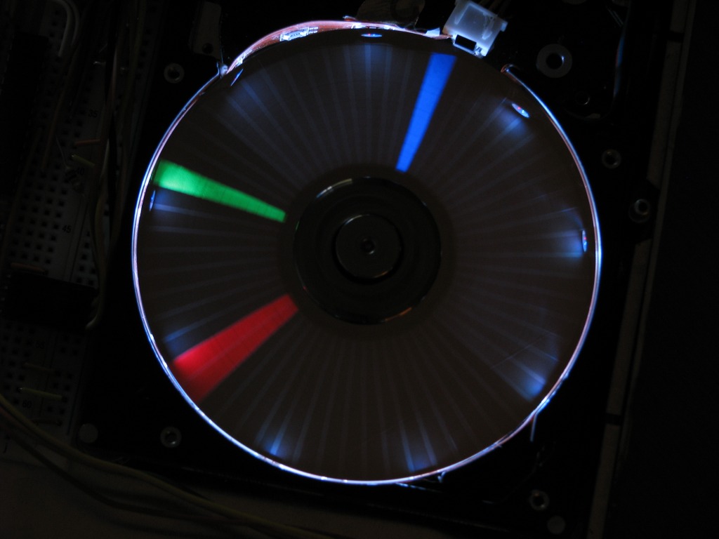
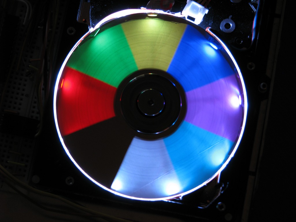
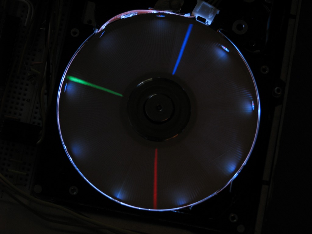
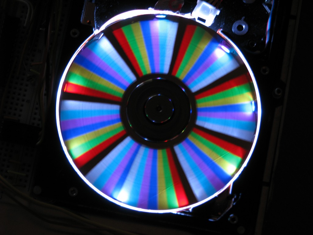
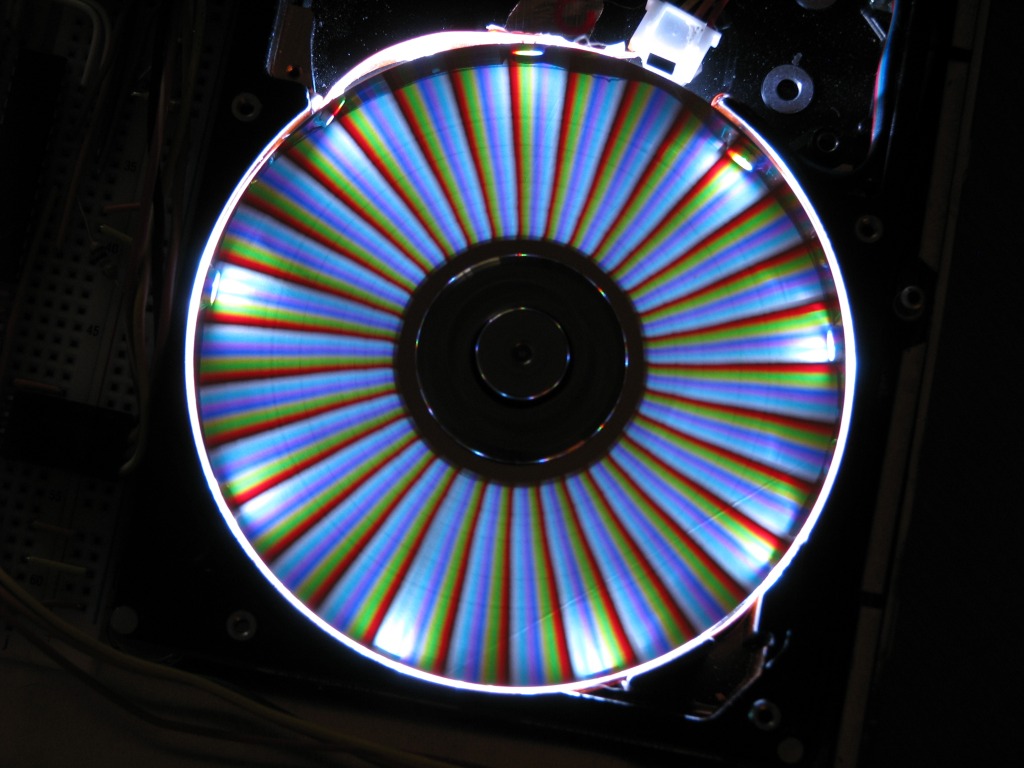
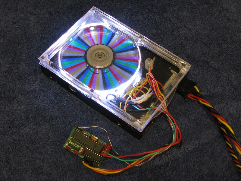
The clock works by removing the top of the hard drive and cutting a slot into the platter. Then lights are mounted underneath and flashed as it spins. By timing it right you can create the illusion of clock hands, color bars or other designs.
|
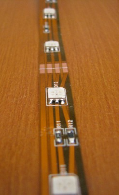
What really decided me on building this was coming across this LED strip from
Super Bright LEDs.
An 18" strip with 30 tri-color LEDs for $20 was just too good for me to pass up.
It runs on 12v which was perfect since the hard drive needs both 5v and a 12v supply, so it hooked up nicely. When I make the next version I will replace the reistors with lower values so I can run it off 5v and reduce the number of wires by a few. It comes with a self adhesive strip on the back, so putting it on was easy too. I wish I had a whole roll of this stuff, very fun to play with. This meant I did not have to drill holes in the sides of the case, and could do the wiring internally. |
Theory
|
I have quite a few magnets lying around so my first thought was I could
eliminate 2 of the three platters by using a magnet on the top platter and a magnetic sensor to
detect it. The one disadvantage to this method is I now have to cover the entire bottom of the drive
case in white instead of just one strip of white tape. If everything is flat it works well. If
things stick up at weird angles you get shadows.
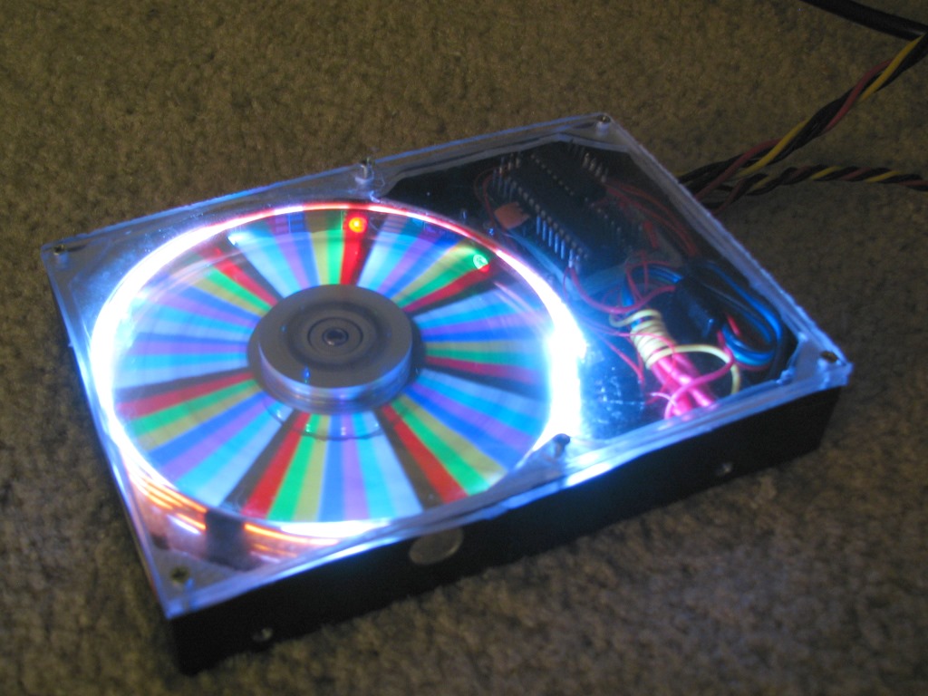
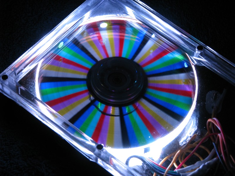
My second change was using a led strip I came across while browsing. This upped the colors to three, and means I have 7 to work with my mixing them together. I had hoped to have a much brighter image but the LED's focus is straight out, not angled down like it should be. A cone shaped white surface to project them onto would be a big improvement. The clock works because the human eye does not see frequencies above 60 or so as blinking, but as a solid color. This is how we see a TV picture as a full image and not a series of lines being drawn across it. At 5400 RPM this drive spins just over 90 times a second, plenty fast enough to fool the eye into thinking it sees solid hands and not a spinning bar of light. And the last change is using a 3.5 inch drive. I simply don't have a bigger one, and I wanted something somewhat quiet as well. Eventually I hope to cover the top with plexiglass and have a quieter clock once it is all sealed up. The code I wrote myself, as I wanted to be able to add new types of displays and patterns to it. It does not assume the drive spins at a fixed rate, but times each revolution and calculates the delays needed to flash the display correctly. I use a timer interupt to decide when to turn on or off the LEDs. I had used a loop comparing the timer value and it worked, sort of. Every few seconds it would glitch and the hands would quiver annoyingly. I was never sure what caused it, but switching to timer based interupts made it rock solid. It's fun to slow the disk down with a finger and watch it still maintain the image until the disk goes too slow for the 16 bit timer to handle and starts overflowing. |
|
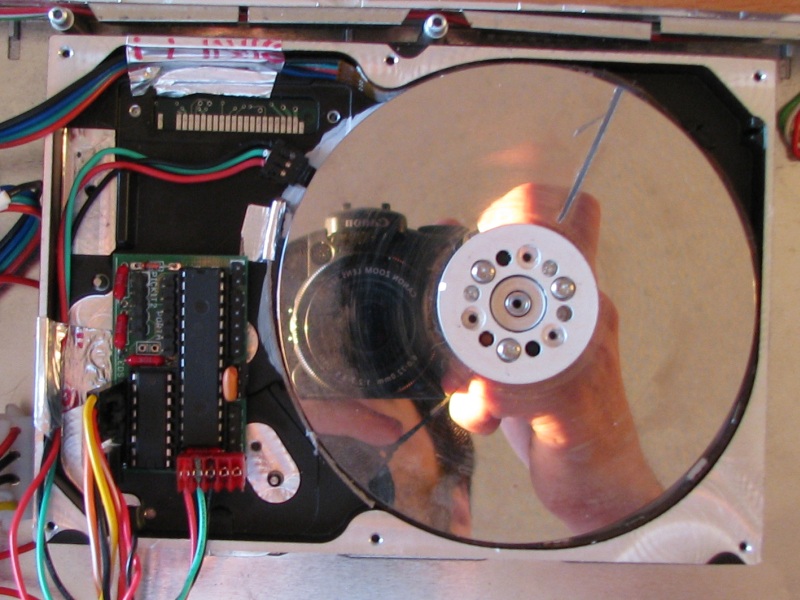
Construction
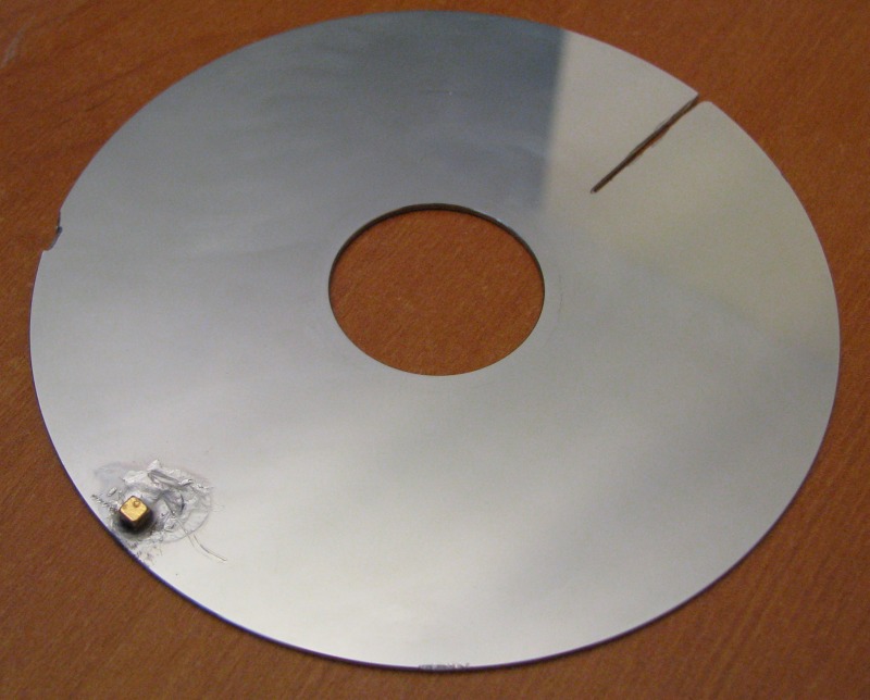
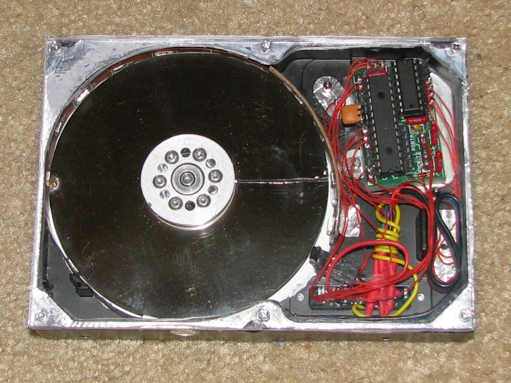
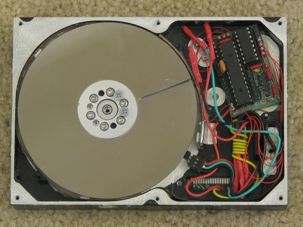
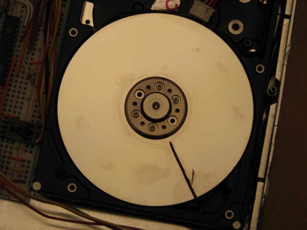
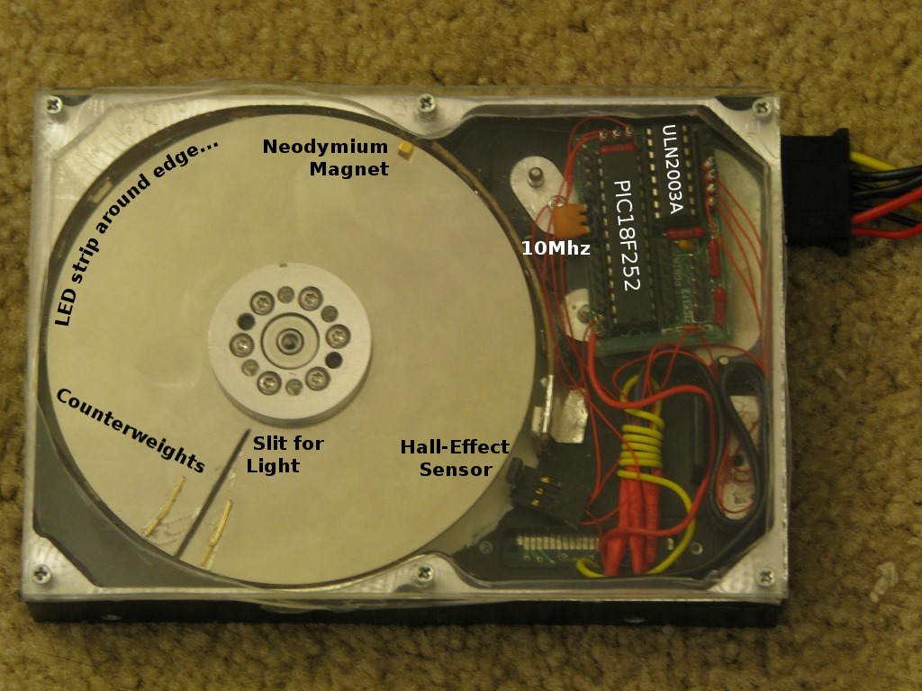
| I cut a slit into the platter with a dremmel and glued a magnet to what will be the underside of the drive. This will trigger a Hall-Effect magnetic switch that lets the PIC know the disk has made a rotation. This is used both to align the clock hands and time the rotation so it knows when to flash for the hands. |
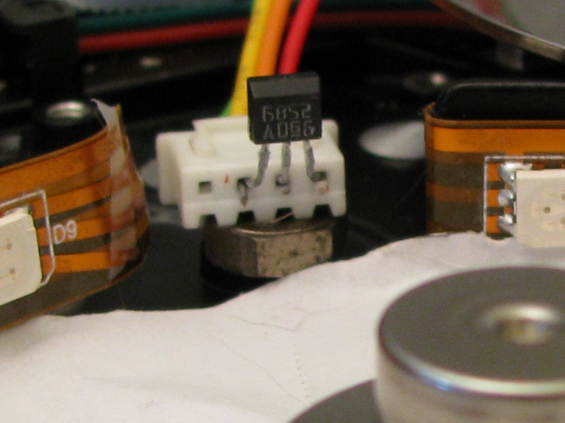
| Here is the Hall-Effect sensor. I stuck it in the end of a hand cable with a convienent connector, bent it up at a 90 degree angle and glued it in place. If it is not secured well it can vibrate and make the clock hands jitter and shift. I used a DN6852N from Digi-Key but any Hall-Effect Switch will work. |
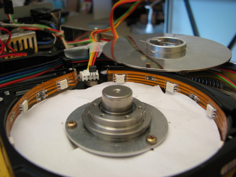
| I used a flexable LED strip that is taped to the inside rim of the platter. There is just enough clearance for the very thin strip to fit in the space between the platter and the rim of the case, and the LEDs themselves are below the platter so they do not get in the way. The strip I used runs on 12v with one wire for common and the other three to control the red, green and blue led's in each package. You can see the seperate LEDs in each white case as the three dots in a triangle. I also put some white paper underneath for the LEDs to shine on. White paint would work better. The strip is self adhesive and sticks well. |
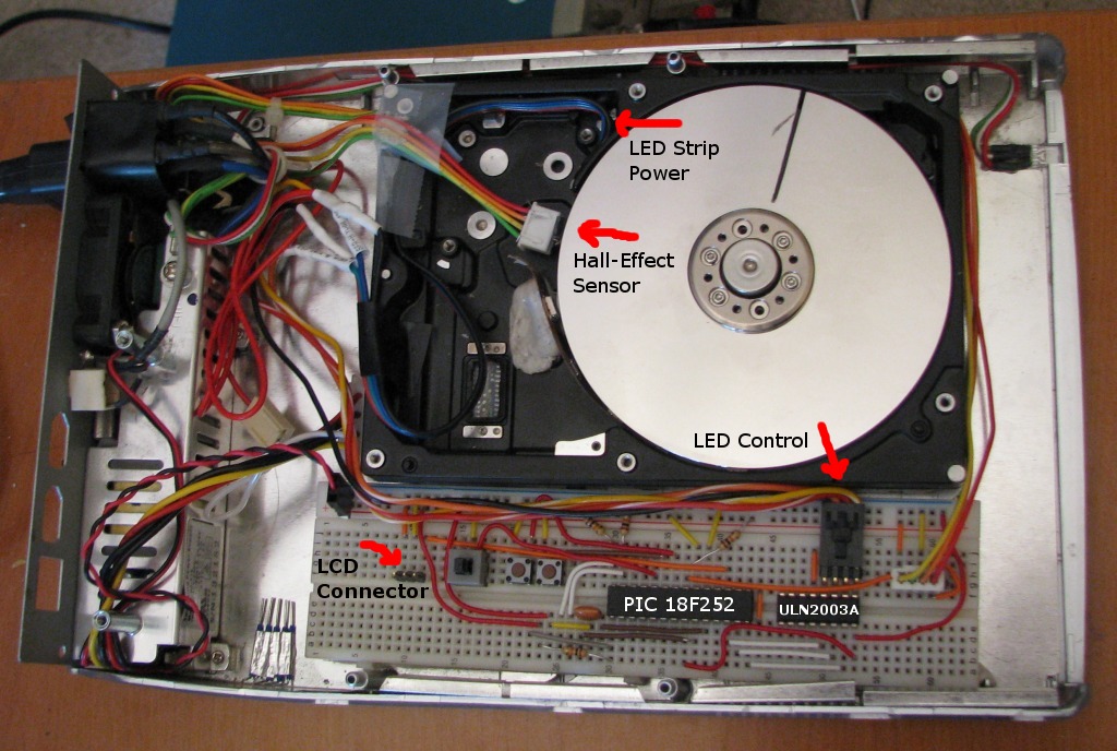
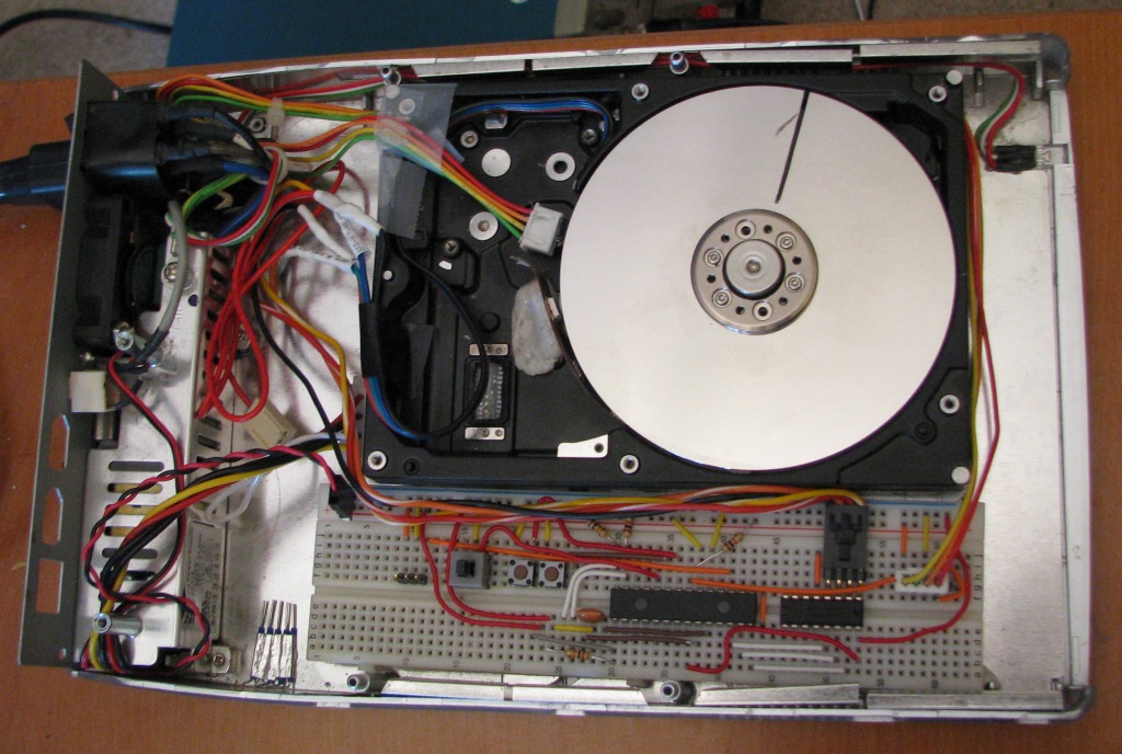
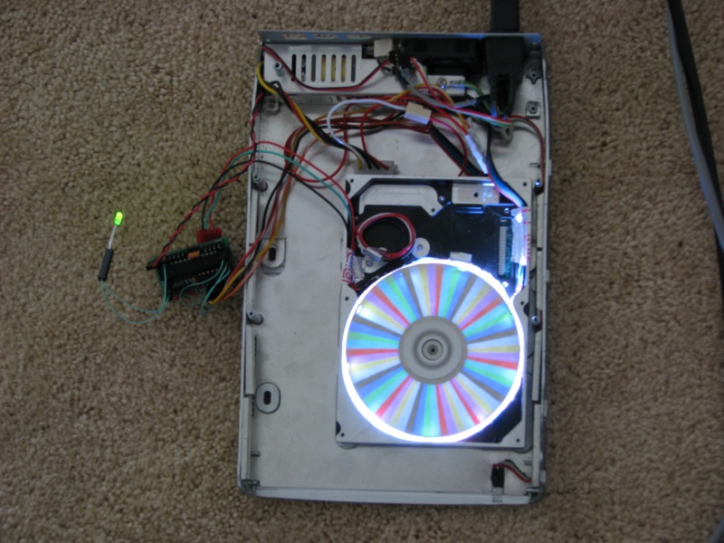
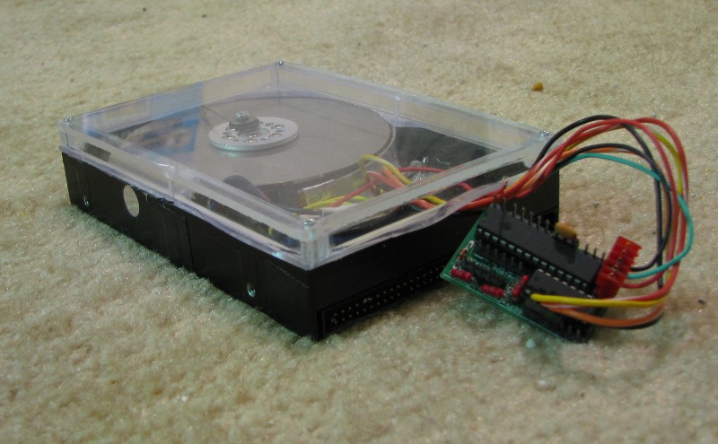
| Once assembled and tested I mounted it all in a 5-1/4 external drive case with the USB interface removed, leaving just the power supply. At some point I plan to make a small circuit board and try and fit all the electronics inside the drive itself. There is JUST enough room. |
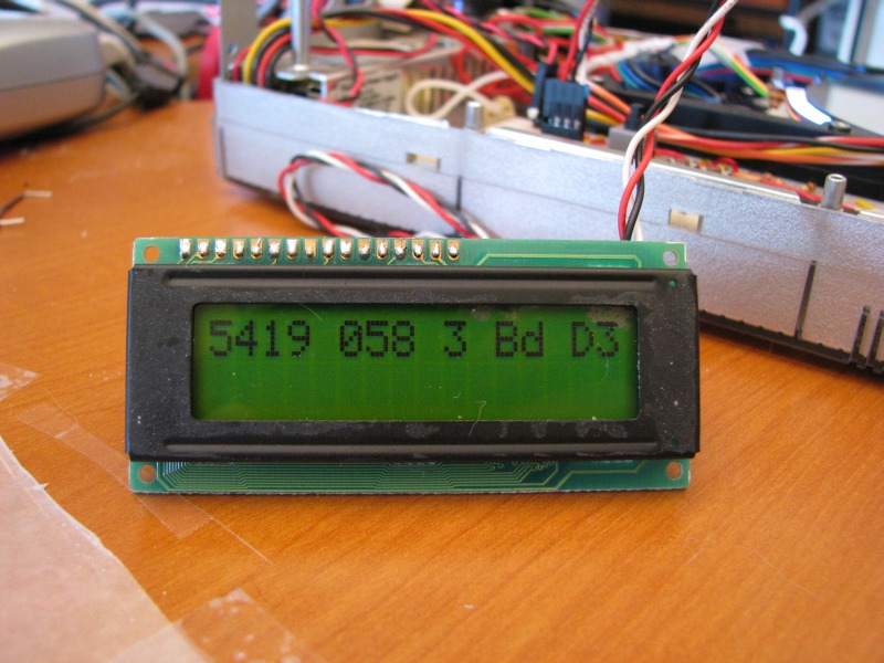
| I added a LCD first to print some debugging information when I was troubleshooting my code and the hardware, and later as an interface used by the three buttons to set the time and change various display paramaters. Much more fun to hit buttons than to recompile and re-flash the chip every time I wanted to make it do something else. You can see it showing the RPM of the drive, 5419. And they said it was a 5400 RPM drive, liars! :-) |
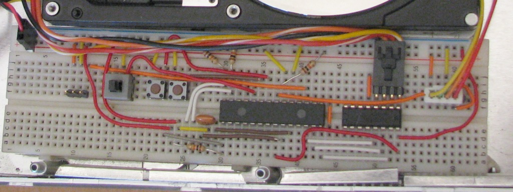
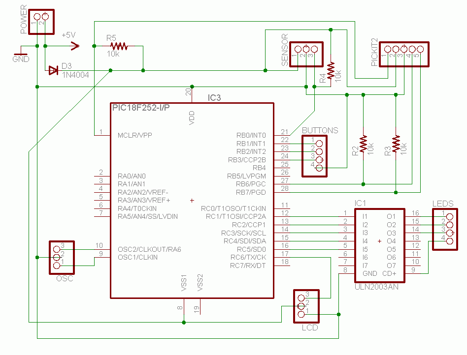
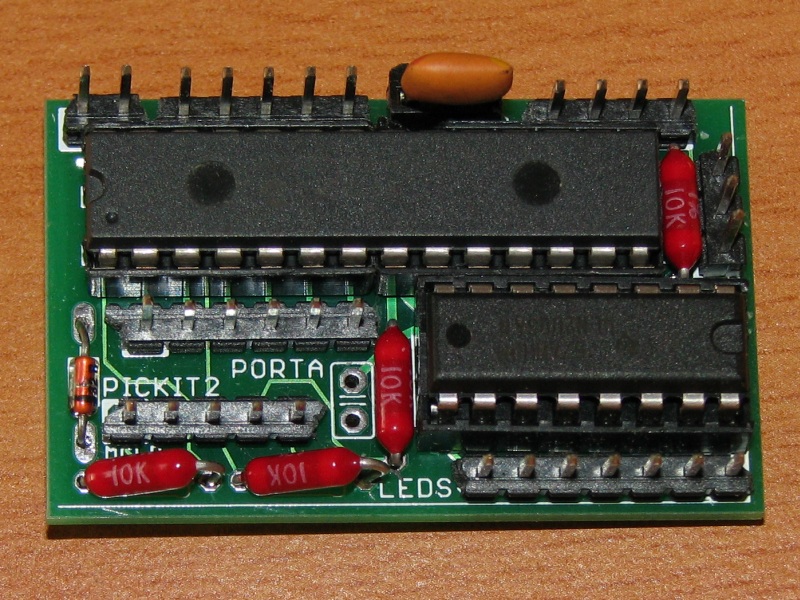
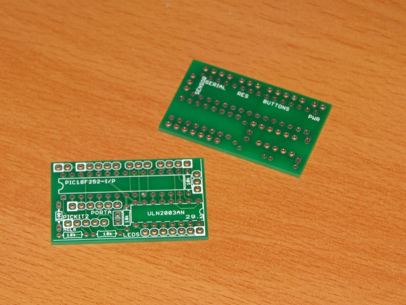
| The circuit is fairly simple. One pin on the PIC18F252 is used as an input to watch for the platter rotation, and three output pins are used to turn on and off the LEDs. Since there are so many LEDs in the strip and it also runs on 12v, I use a ULN2003A darlington transistor array to supply the current. The bottom three connections on this chip are the TTL inputs, the top left three are the outputs and the rightmost pin is the +12v supply current for the LEDs. A serial LCD header and a few buttons to select display modes and options complete the hardware. |
Sadly the drive shown is a replacement for my dirst drive which shorted out due to some metal sneaking in under the drive while it was on. The current drive is not well suited, and I had to raise the hard drive motor and elivate the disk above the spindle to make room. But it works until I can find a new drive.
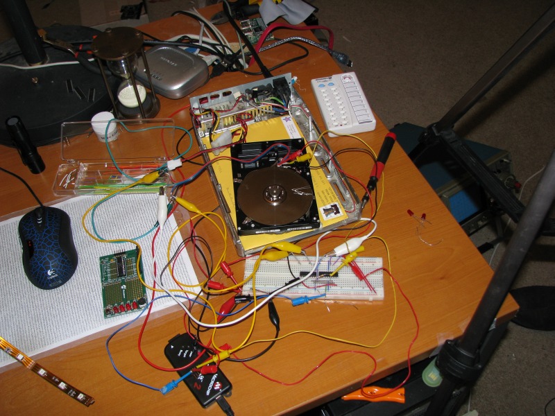
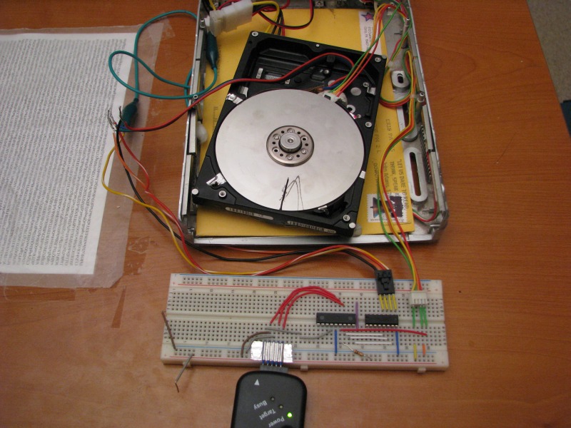
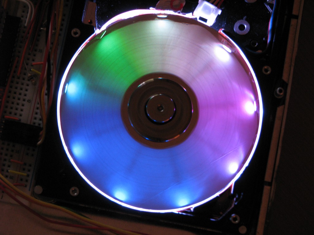
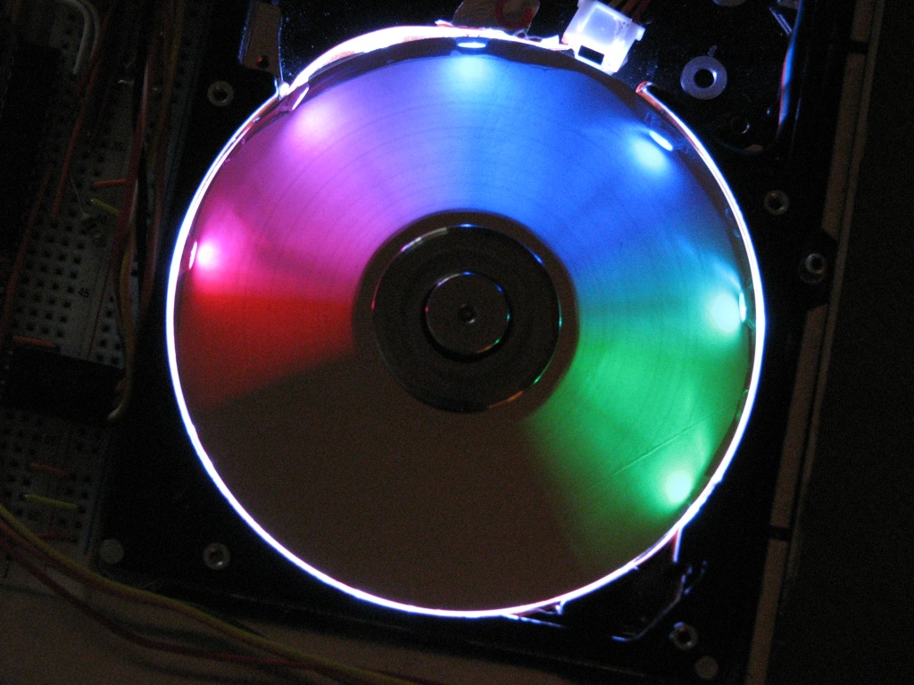
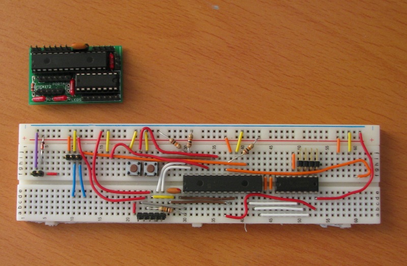
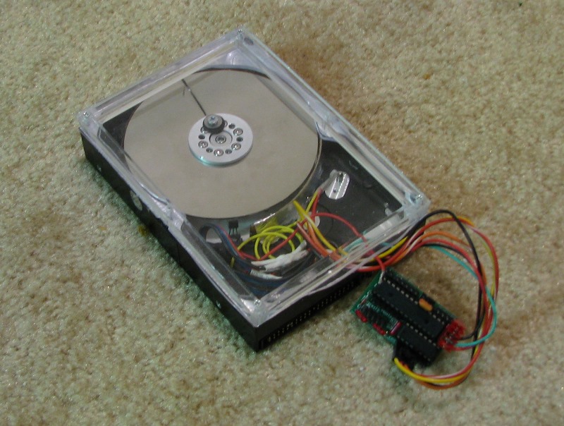
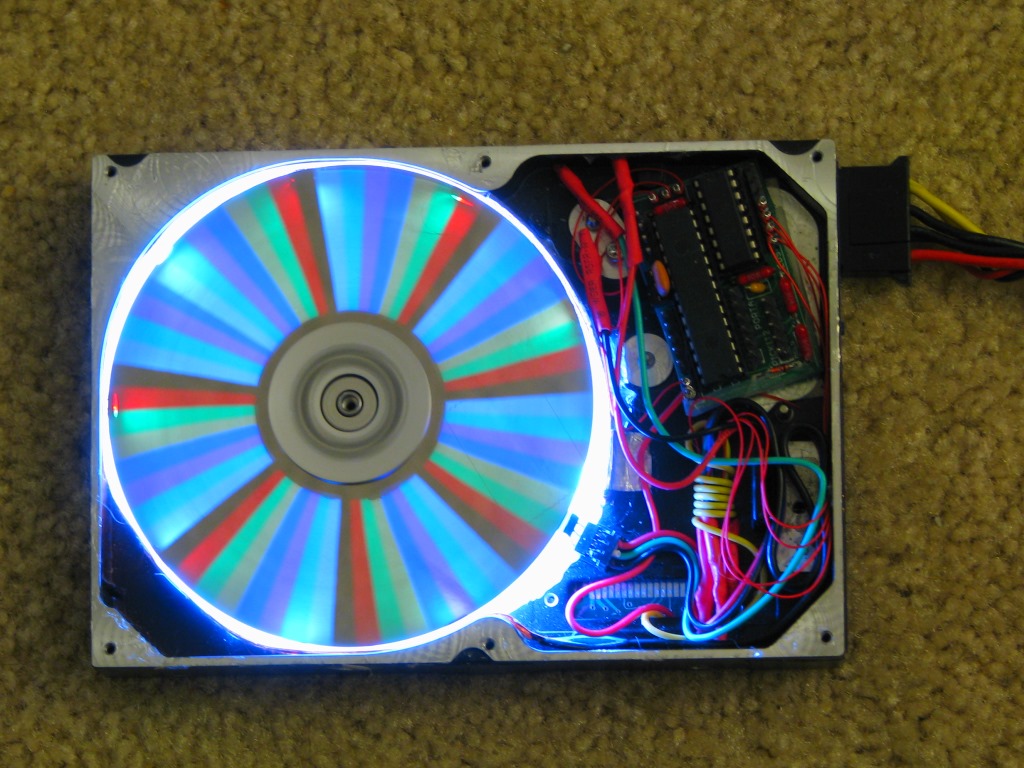
Below are two shots of the project, one while I was still working on getting it up and running, and the second aftter cleaning up the design. Nothing is worse than dozens of little wires running all over your desk just WAITING to short out, come unclipped or get snagged by your <censored> cat. The third is the 'finished' product. I switched from the 16F88 to the 18F252 for the speed and additional timers the bigger part offers.
Success!
Pictures
Click on a thumbnail to view the full sized image...
Links and References
Alan Parekhs Hard Drive Clock - This is the first POV hard drive clock. It's what got me interested in making one myself. What a great idea.
Clock by Jason Amsel and Konstantin Klitenik - A pair of students made this one using a 3.5" drive and RGB LEDs, and a nice big touchscreen! Everything is better with a touchscreen.
A German Clock - This is a very cool mechanical design and is also a clock you could actually have on your desk. You can translate it to english if you can't read german.
I am also building a 2.5" Hard Drive Clock from a laptop drive with good progress so far.
Updates...
A New Hope!
June 2008 - I found a new drive with a better interior and moved the electronics to it. I also had a small circuit board made by BatchPCB that will fit inside the drive. It all works, but I still have to do some final work to get the wiring under control, secure the board to the drive, make a clear cover for the drive and run some wires for power and switches.
A Well-Balanced Project
Dec 2008 - I finally did some work to quiet this thing down. First I balanced the disk with the help of an accelerometer and oscilliscope to measure the vibration and added and subtracted balance weighting on the drive until it ran smooth. Then I built a plexiglass enclosure. I need to re-wire it with smaller wires so I can fit all the electronics inside.It's louder than the average hard drive, but not by much! And that is far better than the ear splitting noise it produced before. Once I don't need to run wires ouside the case it will be a bit quieter as well, as noise escapes from the gap currently. But I am quite happy with the results.
Re-Wired and Slimmed
Jan 2009 - I still need to find some nice, tiny connectors to make it easier to swap stuff around, but it now all fits inside the case at last. It's nice to see it the way I first envisioned it without all the wires and proto-boards and components sticking out all over the place!I also thinned it out in the last three photos. Reversing the platter so the magnet was on top let me lower the disk, and supergluing counterweights let me remove the screws in the spindle which stuck up high. So the top is now just one rectangle of acrylic and a strip of vinyl underneath. It makes it easier to see how it all works too, with the magnet visible on the top of the disk.
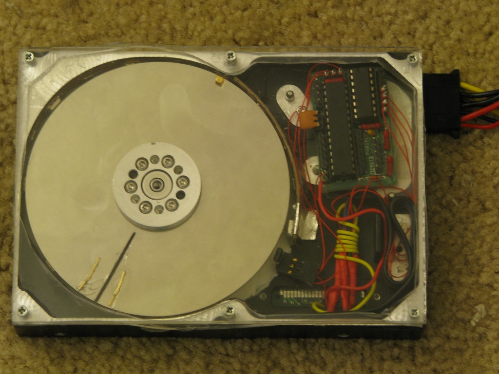
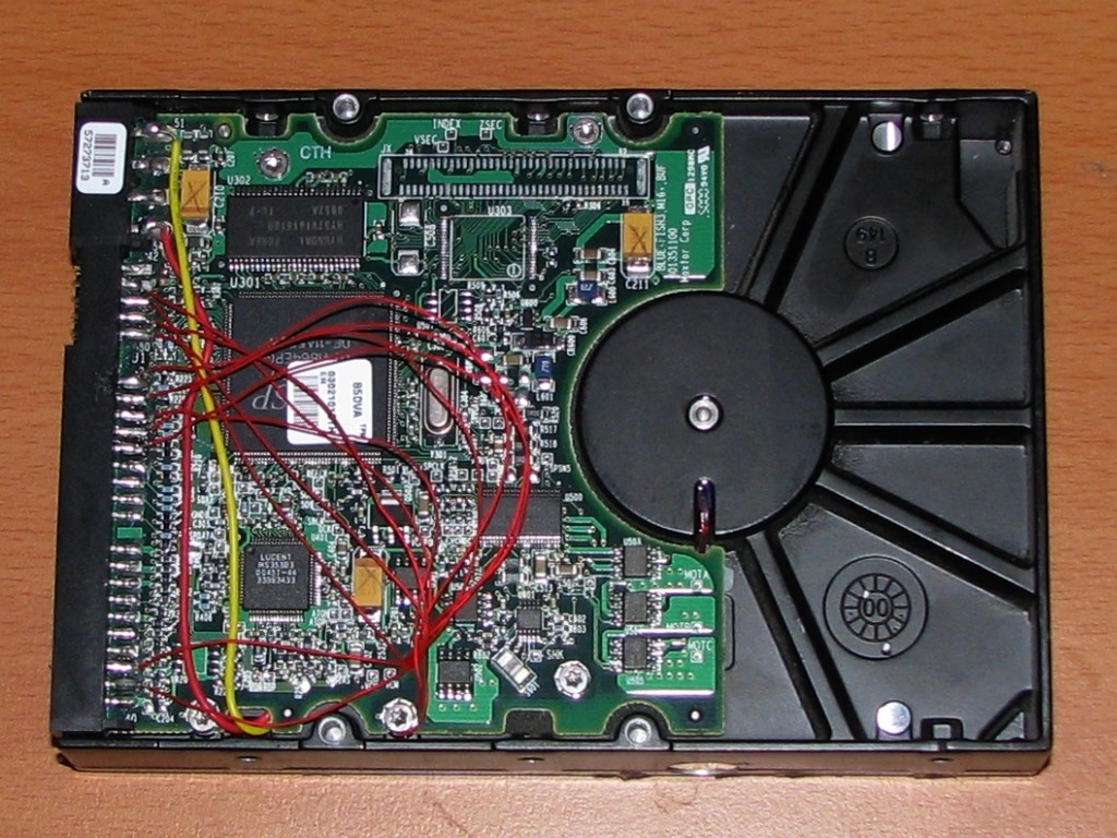
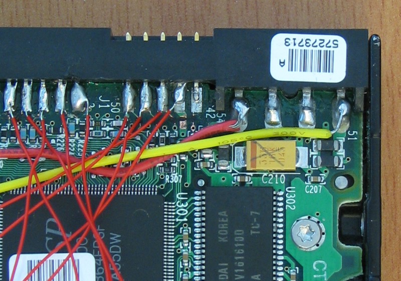
A bit more reworking and I now have all the connectors re-wired to the pins on the side of the drive. I just used a sharp edge to scrape away the traces to disconnect the pins from the driver board and ran the small wire wrap wire through a convienent hole. Now I can run it with the top closed and still reprogram it, press buttons and hook up the LCD. I also got rid of the counterweights on the disk and put them in the spindle itself, which has holes just for that purpose.